History
The history of adsorption dates back to 1848 when Faraday produced cooling using adsorption refrigeration phenomena using silver chloride to adsorb ammonia. By the late 1800’s, liquid ammonia absorption refrigerators were commonplace. Even Albert Einstein and his former student, Hungarian-born American physicist Leo Szilard first patented their own design for an Absorption refrigeration device in 1928. In the 1960’s, commercial absorption chillers using lithium bromide salt and water were commercialized, but were found to be difficult to operate with high maintenance costs.The commercialization of Adsorption Chiller happened in Japan using silica gel and water pair in 1986. CCHP Adsorption machines were used in Germany in the year 2000. An American company developed large Adsorption Chillers using Silica Gel and water pair in 2008.
2015 … in India
Now being produced in India for the first time, adsorption chillers using solid silica gel desiccant and water refrigerant operate over a wide range of conditions and deliver low maintenance costs.
For applications where waste hot water is abundant, adsorption chillers offer building owners an alternative to vapor absorption machines (VAM’s) that use lithium bromide liquid desiccant. For instance, these machines can be stopped and restarted at any time with no problems. Similarly, pumps and water flows can be stopped and restarted at any time without damaging the machine. In fact, the machines are so rugged there is almost nothing that can be done to damage them. As long as the factory provided vacuum pump is allowed to operate normally, the machine should be able to operate 25 years or more with no major components being replaced.
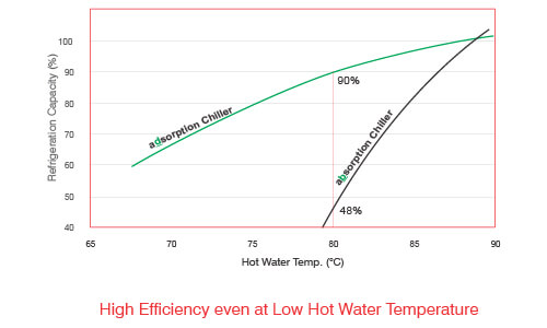
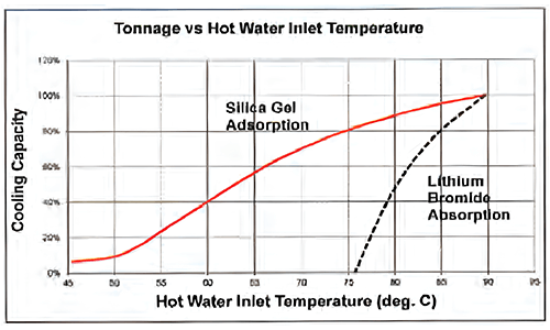
One of the major benefits of silica gel adsorption chillers is the ability to operate well at mild hot water temperatures as shown in the graph.
The chart 80°C, adsorption chillers are the only practical choice. These temperatures are commonly found in industry. Also consider that with many heat recovery applications, the temperature of the hot water will fluctuate over time as the building’s operating conditions change. The lowest operating condition should be considered. adsorption chillers offer the owner the ability to operate the system over a very wide range of conditions and still obtain cooling.
Secondly, adsorption chillers can produce chilled water down to 4.4°C, which is colder than a VAM can provide. This is advantageous in many industries. Lastly, adsorption chillers can operate with higher temperature cooling water from a cooling tower. In humid climates, this is extremely important since temperatures will be higher than the standard chiller design conditions. Although the capacity will be slightly reduced, the chiller will continue to operate. For example, at nominal conditions but using 35°C cooling water, a chiller will provide 82% of nominal capacity. If the chilled water temperature is reset to 12°C output with 35°C cooling water, the capacity will rise to 109% of nominal capacity exceeding its nameplate rating. Computer selections are available for any temperature and flow rate combination that is desired.
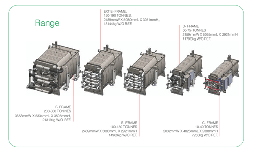
Chillers are offered from 3 to 330 tons of nominal capacity. Larger systems can be built by placing multiple chillers in parallel.
The primary internal components from 10 to 330 tons are the same. Larger chillers simply use more evaporator tubes, condenser tubes, and adsorbent heat exchangers. This reduces production inventory and lead time through component standardization.
Each chiller has its own PLC to monitor operating conditions and maintain the desired chilled water set point by controlling the internal water flows of the machine. As internal flow is restricted, another valve on the chiller opens to maintain constant water flows from the external pumping system. Variable flow pumping systems are also acceptable. The chiller has few restrictions regarding flow rates and cooling water temperature since the internal silica gel is already a solid and never moves. The desiccant is a stationary, solid state sorbent and is very forgiving of system changes.
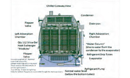
The adsorption cooling process works by moving refrigerant (water vapor) from the low pressure evaporator to the high pressure condenser. This is accomplished in two steps by using the silica gel sorbent. When dry, the silica gel has an affinity for water vapor, whose molecules stick to the surface of silica gel like magnets through polar bonds. During adsorption while the silica gel is externally cooled by water from a cooling tower at 30°C flowing through heat exchangers, the vapor is adsorbed onto the surface of the silica gel. This creates a vacuum in the chiller and causes liquid water in the evaporator to flash to vapor, thus cooling the remaining liquid. The cold refrigerant water flows over the copper evaporator tubes that contain the chilled water flow, which is therefore cooled. This process continues until the silica gel becomes saturated with water after a few minutes.
There are two chambers filled with silica gel packed in heat exchangers. While one chamber is adsorbing water vapor, the other chamber is being heated with hot water flowing through the heat exchangers, which drives the water out of the silica gel into the condenser section. The vapor condenses on the copper condenser tubes and liquid refrigerant water is collected and sent back to the evaporator. The desorption process continues until the silica gel becomes dry.
At this time the chiller opens a valve to equalize the pressure between the two adsorption chambers. This allows the hot chamber to dry out even further. Plus, it equalizes the temperatures between the two chambers, increasing the thermal efficiency.
The valve then closes, and hot water is flushed from the heat exchanger tubes on one side to the other side. This also increases the efficiency. The PLC then instructs the butterfly valves on the chiller to swap the chambers that receive hot water and cooling water. The chamber that has dry, hot silica gel now is cooled with cooling tower water. The dry, cool silica gel rapidly adsorbs all the vapor in the chamber, causing an internal barometric damper to open allowing cold refrigerant vapor from the evaporator chamber to enter extremely fast. Simultaneously, the other chamber is using hot water to regenerate and dry out the silica gel. This batch cooling process repeats every 5 minutes indefinitely until the chiller is turned off.
If the chiller is over cooling the chilled water, the PLC will adjust the butterfly valves to reduce the rate that the silica gel is cooled and it will also reduce the use of hot water in the other chamber to reduce the cooling potential from the gel. The chiller runs autonomously with logic programmed into the PLC. Seven standard steps of capacity control are built into the machine.
The refrigerant is a closed system just like any other refrigerant circuit in a chiller. The refrigerant water is plain tap water from a faucet and can easily be replaced if needed, though replacement is unexpected for most applications. No other additives or chemicals are used in the chiller.
The liquid water from the condenser is delivered to the evaporator through an inverted U trap. The height differential between the water in the riser and the down comer holds back the pressure from the condenser, thus maintaining a liquid seal between the chambers.
We see the pressure-enthalpy diagram for water, which is the refrigerant used in the adsorption chillers. The red arrows show the process that water takes during the refrigeration cycle inside the chiller. Starting with water as a liquid leaving the condenser, (upper left side of the phase diagram), we have water at a pressure of about 1.0 psia and a temperature of around 35°C. The water is delivered at 0.1 psia to the evaporator area of the chiller.
The refrigerant evaporates under low pressure as silica gel adsorbs the vapor above it. The evaporating water removes energy through the latent heat of vaporization of the water at the rate of 2257 kJ per kg. As the water evaporates, it moves from left to right along the bottom of the phase diagram to become heated vapor at a pressure of 0.1 psia.
At this point the water is exposed to a desiccant, which when dry has a high affinity for the water molecules. The desiccant adsorbs the water molecules in the space around it at nearly the speed of sound and lowers the pressure further. When the desiccant becomes saturated, the chamber is then sealed away from the low-pressure part of the system. The pressure and temperature in the desiccant bed are then raised by running hot water from the waste heat source through copper tubes to heat the aluminum fins located in the packed desiccant beds.
When the desiccant reaches a high enough temperature, the desiccant starts to release its water molecules and the pressure in the chamber begins to increase. Hot water continues to run through the desiccant bed and heats the desiccant up to around 95°C at a pressure of 1.0 psia. On the diagram, we can follow the red line from the lower right corner of the phase diagram to the upper right portion of the phase diagram.
At this point, a barometric damper automatically opens in the top of the chamber and the water vapor moves to the condenser chamber. The water is then condensed in this chamber as it comes in contact with a set of copper tubes that are cooled to around 35°C. Once the water is condensed in this upper chamber, the process starts again with the refrigerant flowing back to the evaporator through the inverted trap.
Common applications for the chiller include anywhere that waste hot water is abundant such as on-site power generation, industrial processes in factories, solar thermal fields (primarily found in cold climates), data centers, and power generation stations.
The most common application is on-site power generation from both diesel and natural gas fired engine generators. The jacket water that cools the engine block can be used directly.
If more heat is desired, an exhaust gas heat exchanger can be installed to produce more hot water. Process waste heat from industry is also a great source and could include food cooking and frying, glass production, steel production, rubber and plastic processing, refineries, power generation, and any process that uses water cooling near 100°C.
Current customers include a potato chip frying company, two US embassies with on-site diesel generators, a luxury shopping center in the Pacific with diesel generators, the “Zero Carbon” building in Hong Kong that uses biodiesel from kitchen fryers for on-site power production, four large solar thermal cooling applications in North America, and in fabrication is a 75-ton chiller for a solar thermal project for a university in Turkey.
For applications where waste heat is free and abundant, the chillers can offer an attractive return on investment. Compared to a water-cooled mechanical chiller, a net savings of about 0.5 kW/ton can be obtained. Assuming a customer pays $0.12 / kW-hr for electricity, a 300 ton chiller operating continuously could save over $150,000 per year in avoided electrical costs. If comparing to an air-cooled chiller, the savings will be even higher.
When comparing a vapor absorption machine, we must look at life cycle costs since VAM’s also save the same amount of electrical energy. The expected life cycle of an adsorption chiller is 25 years or more, requiring only minor maintenance and inspection. No tube replacements or other major repairs are anticipated. However, VAM’s require tube replacement after just a few years, and have been known to be replaced after 8 to 10 years of service. Once the total life cycle costs of repairs and replacement are considered, the adsorption chiller proves to have a significantly lower lifetime cost and is the better long-term investment.
A typical table for payback calculation for a 100 TR adsorption chiller in comparison to electric chiller is shown below subject to the condition that waste hot water is available. Here the consideration is based on 16 hour operation per day & for 350 days in a year. This time period will change depending on price of energy, hours of operation etc.
| Annexure – 1 – Payback period in comparison to Electro-Mechanical Chiller | |||||
| Sr. No | Description | Unit | Adsorption Chiller | Mechanical Chiller Water cooled | Mechanical Chiller Air cooled |
| 1 | Chiller Capacity | TR | 100 | 100 | 100 |
| 2 | Input Energy | – | Hot Water | Electricity | Electricity |
| 3 | Power Consumption. | ||||
| A | Chiller | kWh | 0.80 | 75.00 | 110.00 |
| B | Power Consumption for Balance of Plant. | ||||
| B1 | Chilled Water Pump power consumption | kWh | 7.15 | 7.15 | 7.15 |
| B2 | Condenser Water Pump power consumption | kWh | 5.98 | 2.97 | 0 |
| B3 | Cooling Tower Fans power consumption | kWh | 8.88 | 4.42 | 0 |
| B4 | Hot Water Pump power consumption | kWh | 6.20 | 0 | 0 |
| Total Power Consumption Chiller + BOP ( A+B) | kWh | 29.00 | 89.50 | 117.20 | |
| 4 | Net Power Cost at site | Rs/kWh | 8.00 | ||
| 5 | Operating Hours | Hrs/day | 16.00 | ||
| 6 | Total days of operation per year | days | 350 | 350 | 350 |
| 7 | Total hours of operation per year | Hrs/year | 5600 | 5600 | 5600 |
| 8 | Annual Energy savings compared to Electro-mechanical chiller | Kwh | – | 3,38,800 | 4,93,920 |
| 9 | Annual Energy Cost | Rs | 12,99,200 | 40,09,600 | 52,50,560 |
| 10 | Maintenance Cost | Rs | 20,000 | 2,00,000 | 2,50,000 |
| 11 | Total Operating Cost per annum | Rs | 13,19,200 | 42,09,600 | 55,00,560 |
| 12 | Payback period v/s Electro-mechanical chiller | Years | – | 3.63 | 2.34 |
The life cycle cost calculation shows that the cost of ownership of Adsorption chiller is almost half of the Absorption chiller after considering the replacement of Absorption chiller in 8 years, maintenance cost & operating cost.
The IRR is calculation for Adsorption chiller is done considering the savings in Energy cost v/s the electric chiller. IRR for the same 100 TR chiller is 17.9% as against an IRR of 5.39% for an Absorption chiller.
The Adsorption chiller needs hot water as energy input. Some of the possible heat sources are mentioned here
- Onsite power production e.g. Tri-Generation (CHP), DG Sets, Gas engines
- Radiator – Jacket water
- Exhaust gas heat – Hex required
- Industrial waste heat
- Flue gas exhaust heat
- Boiler condensate
- Boiler blow down
- Process waste heat e.g.
- Refineries
- Power plants
- Food processing, and beverages
- Chemicals
- Pharmaceuticals
- Plastic extrusion
- Pulp and paper
- Aluminum
- Cement
- Steel
- Solar thermal
- Evacuated tube collectors
- Flat plate collectors
- Concentrated parabolic collators, dish and trough
Various types of heat exchangers such as gas/air to water, steam to water or water to water can be used to produce hot water for depending on the availability of waste heat.
The adsorption chillers works under vacuum. It is important to have the workmanship of highest quality for trouble free operation. Leak testing is performed at the factory using helium, due to its small molecular size and rarity in the atmosphere. The adsorption chillers are factory tested for performance. The testing facility needs to have all the utilities including the hot water source, cooling water & chilled water to carry out the tests. World class facilities are being put up in India to meet all these necessities.
Substantial research is being carried out to improve the Adsorber as well as the heat exchanger performance to provide the same output. Efforts are being made to reduce the weight, size of the chiller & price as well. This technology has a great advantage to reduce the carbon foot print by utilizing low grade waste heat that would have gone waste otherwise.
By Wes Livingston, PPI, USA and Ashok Kumar Prusty, Executive Vice President, Bry-Air (Asia)
Wes Livingston is the lead ECO-MAX design engineer responsible for developing the next generation of adsorption chillers.
Professional Activities, Awards, and Honors
The Atlanta Section of the American Society of Mechanical Engineers “Distinguished Speaker,” 2009
Association of Energy Engineers (Georgia) “Distinguished Speaker,” 2010
Ashok Kumar Prusty is the Executive Vice President of Bry-Air (Asia) and has almost 30 years of experience in the field of planning and implementing strategies, increasing footprint in overseas market and top & bottom line growth.
Mr. Prusty is a Mechanical Engineer from Bangalore University and has done his management from Narsee Monjee Institute of Management Studies, Mumbai.