Welcome to Bry-Air
Home
Product
Industrial Desiccant Dehumidifier
Gas Phase Filtration Systems
Plastic Auxiliary Equipment
Lithium Battery Dry Rooms
Adsorption Chillers
High Temperature Heat Recovery Wheels
Others
Industry
Desiccant Dehumidifiers
Gas Phase Filtration Systems
Plastic Auxiliary Equipment
Dry Rooms
Adsorption Chiller
High Temperature Heat Recovery Wheel
Problems and Solutions
Condensation Prevention
Moisture Regain Prevention
Product Drying
Mold, Mildew and Fungus Prevention
Preservation and Archival Storage
Corrosion Prevention, Protection & Rust Control
Aircraft and Munitions Preservation
Ethylene Control
Odour Control
Insights
Exhibition & Seminars
News
Blog
Technical Articles
BryCare
Case Study
Newsletters
Our World
About Us
R&D
Sustainability Policy
Bry-Air-CSR
Careers
Contact Us
Search
18001027620
enquire@pahwa.com
About Us
R&D
Career
Contact Us
Product
Desiccant Dehumidifiers
Gas Phase Filtration Systems
Plastic Auxiliary Equipment
Dry Rooms
Adsorption Chiller
High Temperature Heat Recovery Wheel
Compact Desiccant Dehumidifier
Desiccant Dehumidifier FLI Series
P95° X Dehumidifier
Bry-Air BrySmart® Series (BBS) Dehumidifier
Desiccant Dehumidifier - FLB Series
Tray Dryers
Low Dew Point (LDP) Dehumidifiers
Green Drypurge® Dehumidifier – GDP Series
Compact Dehumidifier BryCool™ Series
Enviroliner
Bry-Air Minipac®
BryShield
DataCenter Air Purifier – DAP Series
Bry-Air Control Room Air Purifier
EcoScrub™ Deep Bed Systems
EcoScrub™ Thin Bed Systems
Bry-Air Ethylene Scrubber – BES Series
Odour Control Unit
Honeycomb Chemical Filter – DRISORB™ Series
BRYSORB™ Chemical Media
Atmospheric Corrosivity Monitor
Corrosion Classification Coupon
Wonder Dryer
Nano Dryer
Hot Air Dryers - HAD Series
Mould Dehumidification Systems - MDS Series
Moisture Minder BRYSCAN™ Series
Centralised Conveying Systems - BCS Series
Auto Loaders BVL (F) Series
Auto Loaders BVL (T) Series
Combo Dryers
Hopper Dryer
Dry Rooms
Adsorption Chiller
BryChill™ Adsorption Chiller
High Temperature Heat Recovery Wheel
Energy Recovery Wheels
Industry
Food and Food Processing
Pharmaceutical
Lithium Battery
Electronics and Electrical
IT, Data Centres and Telecom
Automotive
Power
Leather and Garments
Aviation and Defence
Healthcare and Hospitals
Fertilizer and Chemicals
Pulp and Paper/Printing
PET/Plastic and Packaging
Others
Desiccant Dehumidifiers
Biscuit & Cookies Storage & Processing
Cheese Processing Facilities
Chips, Wafers and Namkeens
Coffee Manufacturing
Ante Rooms in Cold Storage
Confectionery Manufacturing
Dehydrated Food
Spray Drying
Convenience Food
Food Concentrate Processing and Packaging
Humidity Control in Food Processing
Health Food Processing
Honey (Uncured) Drying
Meat Poultry & Sea Food Processing
Mushroom Drying
Seed Drying & Storage
Snack Food Processing and Packaging
Spice and seasoning Drying and Storage
Sugar Manufacturing
Super Markets
Tea withering, rolling, and drying
Tobacco Storage
Yeast Making
Gas Phase Filtration Systems
Ethylene Control in Fruits and Vegetables Storage
Odour Control in Food Processing Plants
Desiccant Dehumidifiers
Clean Rooms
Diagnostic Rooms & Research Labs
Dry Powder / Vial Filling
Gelatin Drying
Penicillin Packaging
Soft Gelatine Capsule Manufacture
Tablet Coating, Compression and Packaging
General Pharmaceutical Manufacturing
Gas Phase Filtration Systems
Odour Control in Animal Research Labs
Desiccant Dehumidifiers
Lithium Battery Dry Rooms
Desiccant Dehumidifiers
Corrosion Prevention
PCB Assembly
Semiconductor Assembly
Gas Phase Filtration Systems
Corrosion Control in Semiconductor Manufacturing Facilities
Desiccant Dehumidifiers
Data Centres & Server Rooms
Gas Phase Filtration Systems
Corrosion Control in Control Rooms
Corrosion Control in MSC and BSC Sites
Corrosion Control in Server Rooms
Corrosion Control in Data Centres
Corrosion Control in Distributed Control System Rooms
Desiccant Dehumidifiers
Engine Testing Rooms
Tyre Creel Room & Wire Storage
Powder Coating Areas
Automobile Parts Storage
Desiccant Dehumidifiers
Equipment Preservation in Power Plants
Switchgear Room
Turbine Storage
Desiccant Dehumidifiers
Garments Storage and Packaging
Leather Storage and Packaging
Desiccant Dehumidifiers
Instrument Landing System
JET Engine Storage
Military Arms and Ammunition Storage
Desiccant Dehumidifiers
Healthcare Facility Rooms
Gas Phase Filtration Systems
Corrosion Control in Healthcare Facilities
Desiccant Dehumidifiers
Fertilizer Bagging Area
Gas Phase Filtration Systems
Corrosion Control in Fertiliser Plant
Desiccant Dehumidifiers
Paper Coating
Printer Roller Drum
Printing, Relief & Offset
Gas Phase Filtration Systems
Corrosion Control in Pulp and Paper Plants
Plastic Auxiliary Equipment
Surface Moisture Drying
Hygroscopic Polymer Drying
Plastic Mould Drying
Plastics Conveying
Desiccant Dehumidifiers
Biodiesel Plant – Caustic Soda Dosing Room
Blasting
Bowling Alleys
Bridges Corrosion
Electrode Storage
Falcon Breeding Areas
Film Storage
Glass Laminating Room / Safety Glass
Ice Skating / Curling Rinks
Jute Bag Manufacturing
Indoor Swimming Pool
Investment Casting Drying
Laboratories and Instrumentation Rooms
Museums & Libraries
Ostrich Egg Incubators
Parachute Drying
Sports Goods
Vessel Lay up
Vintage Car Preservation
Moisture Control in Archives & Museums
Turbine Preservation in Sugar Industry
Gas Phase Filtration Systems
Corrosion Control in Media Broadcasting Rooms
Corrosion Control in Museums, Libraries and Archives
Odour Control in Mortuaries
Corrosion Control in Wastewater and Sewage Treatment Plants
Corrosion Control in Iron and Steel Plants
Corrosion Control in Rail & Metro
Corrosion Control in Petrochemical and Oil Refinery
Problems and Solutions
Condensation Prevention
Moisture Regain Prevention
Product Drying
Mold, Mildew and Fungus Prevention
Preservation and Archival Storage
Corrosion Prevention, Protection & Rust Control
Aircraft and Munitions Preservation
Ethylene Control
Odour Control
Insights
Exhibition & Seminars
News
Blog
Technical Articles
BryCare
Case Study
Newsletters
Our World
About Us
R&D
Sustainability Policy
Bry-Air-CSR
Careers
Contact Us
Home
Industry
Adsorption Chiller
For Waste Heat Utilisation through Adsorption
Product category
Desiccant Dehumidifiers
Gas Phase Filtration Systems
Plastic Auxiliary Equipment
Dry Rooms
Adsorption Chiller
High Temperature Heat Recovery Wheel
Application of Adsorption Chiller
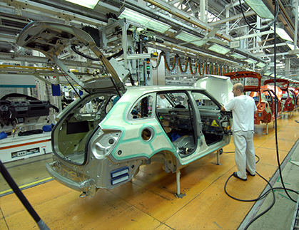
Waste Heat Utilisation in Automobile Plants
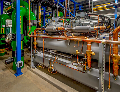
Waste Heat Utilisation from Air Compressors
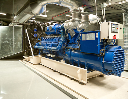
Waste Heat Utilisation from Diesel Generator and Gas Engines
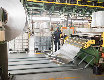
Waste Heat Utilisation in Aluminum Manufacturing
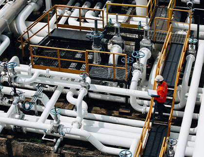
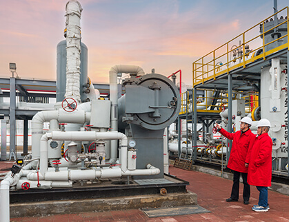
Waste Heat Utilisation in Gas Pipeline
Waste Heat Utilisation in General Industry
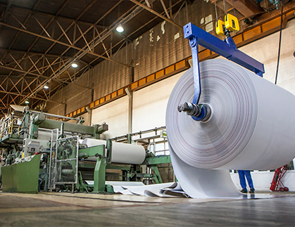
Waste Heat Utilisation in Pulp and paper Plants
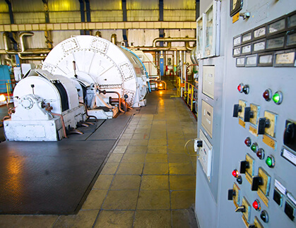
Waste Heat Utilisation in Power Plants
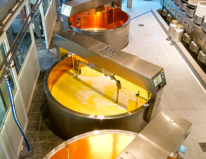
Waste Heat Utilisation in Food & Beverages Industry
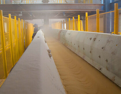
Waste Heat Utilisation in Sugar Manufacturing
Waste Heat Utilisation in Chemical Plants
Let's
Get In
Touch
BryCare
TM
Support
Online
For assistance, please enter your email and phone number below.
×
Chat with Us